Exploring I-Formation and H-Formation Multi-Axis Gantries
There are many different types of gantry robots, which offer the design flexibility to suit a wide range of automation tasks. Two of the most important types are the I-formation (I-form) and H-formation (H-form) gantries. Let’s take a closer look at both designs, along with some typical applications and design criteria.
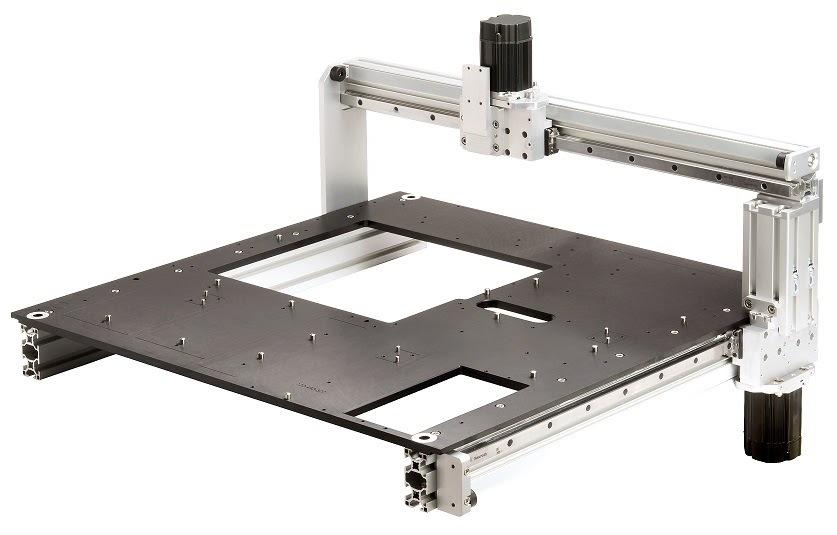
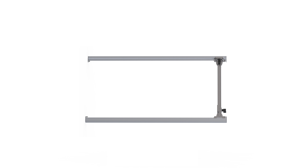
What Is an I-Form Gantry?
I-form multi-axis gantries are typically wall-mounted and include two base axes, a bridge axis and plunge axis, if needed. The bridge axis is typically oriented vertically — parallel with the direction of gravity. Compared to a horizontal bridge orientation, this configuration has the lowest moving mass against gravity, making it the most energy efficient mounting method. It is also the most positionally determinate layout, as the bridge won’t sag due to gravity.
Typical applications for I-form gantries include:
- Aerospace ground tests
- Target positioning for sensor calibration
- Mini-fulfillment operations
- Article inspection, scanning and testing
- Automated storage and retrieval systems
- Indoor agricultural systems — e.g., hydroponic farms and automated harvest systems
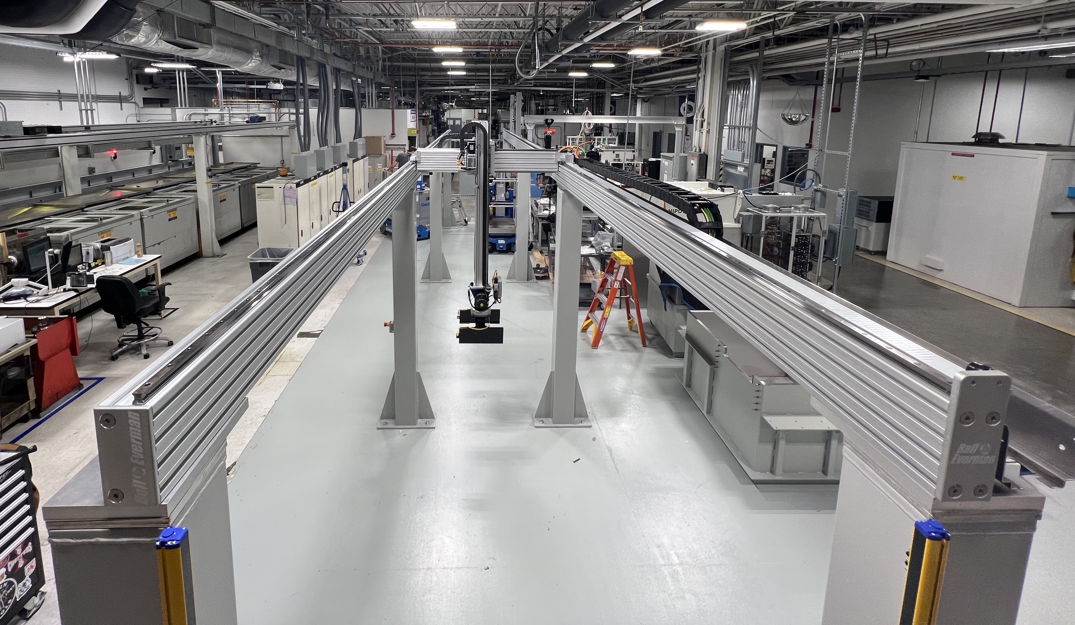
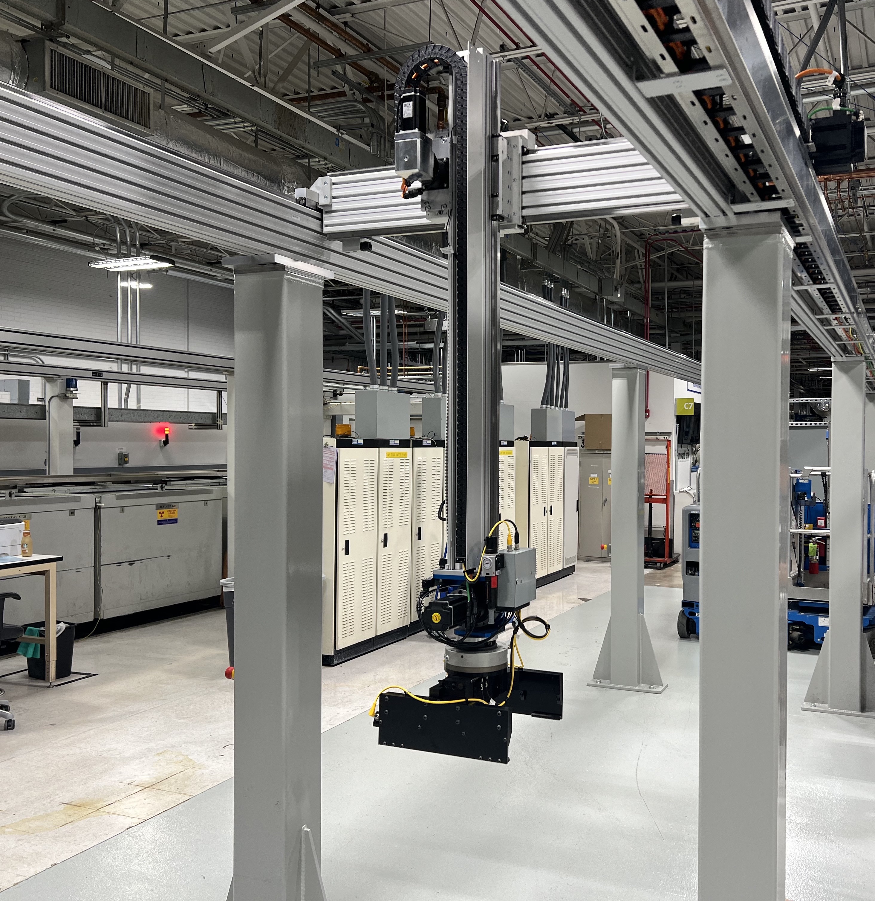
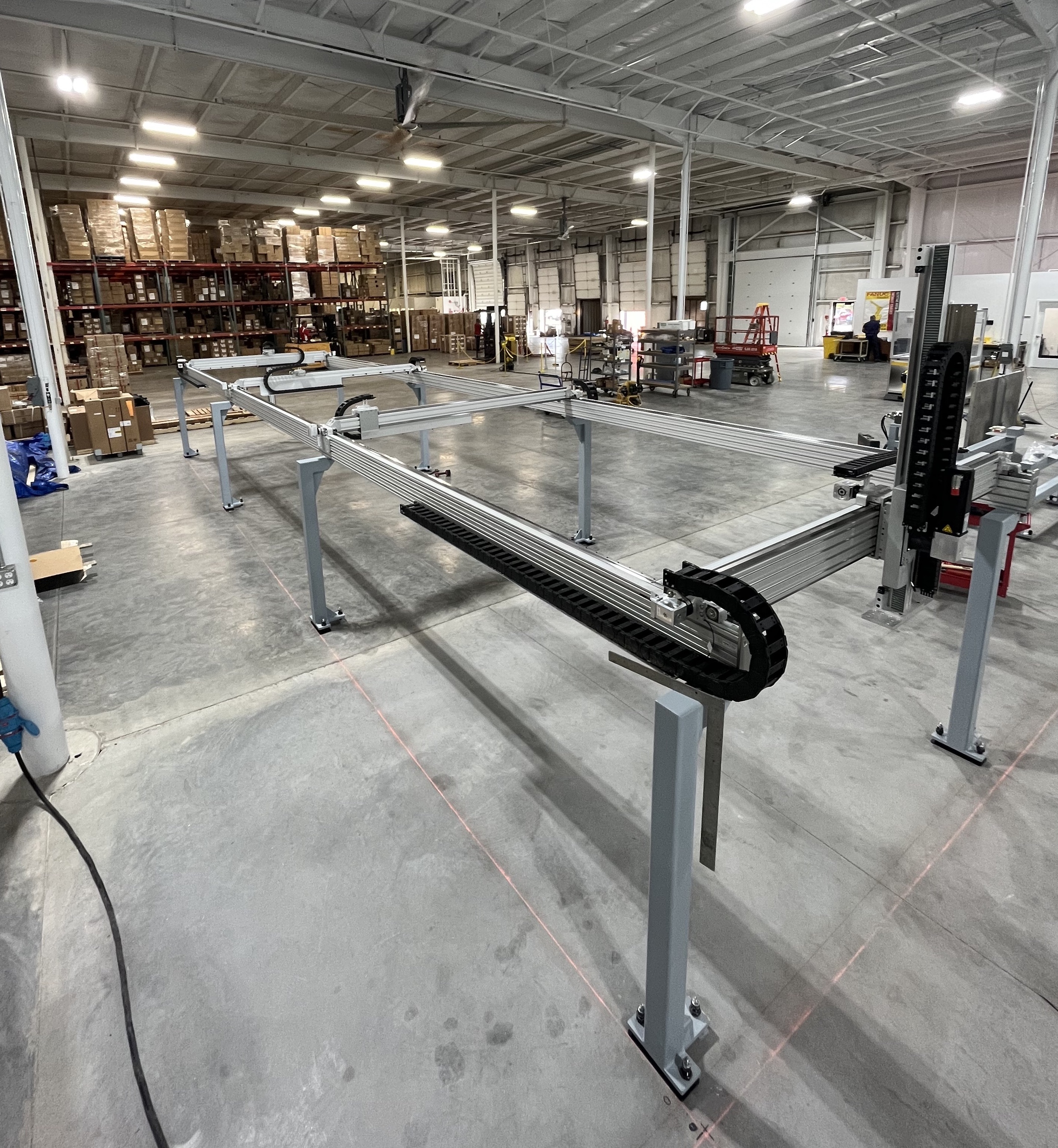
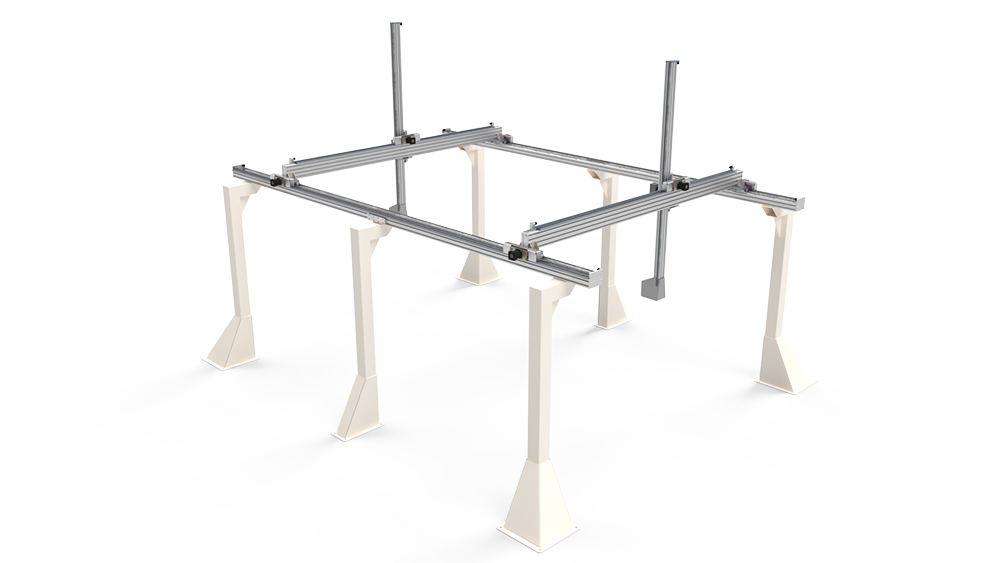
What Is an H-Form Gantry?
H-form gantries, which are a second type of linear multi-axis gantry, include two base axes, a bridge axis and Z-axis, if needed. These gantries are typically mounted horizontally on the plane normal to gravity.
Typical applications for H-form gantries include:
- Material handling
- Pick-and-place systems
- CNC additive and subtractive machinery
- Packaging and de-palletizing
- Print finishing
- Multi-step process automation
- Article inspection and scanning
Design Criteria for I-Form and H-Form Systems
There are some design considerations to keep in mind when engineering I-form and H-form gantries. These include:
The length of the bridge. In our experience, if an I-form or H-form gantry has a bridge that is 1 meter or less in length, one of the base axes can drive the gantry using the other base axis as a follower. If the bridge exceeds 1 meter in length, however, the “racking” — a condition in which the undriven base axis lags behind the driven one — can become more pronounced. In this case, the gantry system should be driven on both base axes.
The addition of multiple bridges. One advantage of ServoBelt™ LoopTrack is the ability to add multiple bridge carriages and entire bridges to I-form and H-form gantries, increasing throughput in the same footprint as a single bridge system. In place of an active belt that runs the length of the axis, LoopTrack technology features a short upper drive belt that loops continuously within the carriage, eliminating belt sag in inverted or side-mounted applications.
LoopTrack offers many performance benefits in gantry applications. It allows the stage to span long travel distances in any orientation. Many independently moving carriages can also share the same chassis and bearing rail.
An ability to scale. ServoBelt gantries come in all sizes but economically shine in larger formats — greater than 2 by 2 meters — and where multiple carriages would be a game changer. By basing the chassis on standard T-slot extrusions, we can mount both the Bosch bearing rails and Bell-Everman custom-molded belt tray on any face. Doing so allows us to meet any application’s required moment and load capacities. Using ServoBelt Linear, we can also engineer large gantry systems with long travel lengths — 100 meters or more.