
Raising the Bar for Artemis Program’s PPE Solar Array Simulation Frame — Part I
NASA’s Artemis Program will send humans back to the moon to establish a lunar ground base and space station. Known as Gateway, the space station will be powered by the Power and Propulsion Element (PPE) module, which utilizes large solar arrays of advanced, multi-junction solar cells to generate 60 kilowatts (kW) of power.
To ensure the PPE’s success, it’s crucial to test the solar arrays with advanced solar simulation that replicates sunlight and measures each circuit’s performance. Engineered by Angstrom Designs Inc., the solar simulator heads must be positioned at numerous points along the length and width of the solar arrays — a process that is usually accomplished using automation frames that consist of linear motion stages. Because the PPE’s solar arrays are so large, standard frames built for conventional array sizes could not provide the necessary vertical and horizontal motion.
At Bell-Everman, we designed, engineered and fabricated a custom motion system that enables the Angstrom Designs solar simulator heads to test the PPE’s solar panels. And to ensure the simulator heads are fully calibrated, we also built the I-formation gantry robot that calibrates and validates the simulator performance against solar cell standards.
Here’s a deep dive into the mechanical challenges of meeting the motion system’s special weight, structural, seismic, lifting, electrical and mobility requirements.
Early Steps
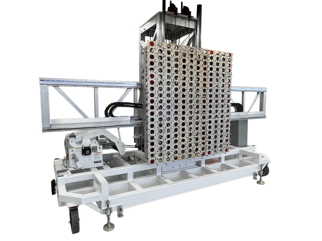
An early design featured two bending tracks — one on the ground and the other roughly 30 feet high near the top of the panels. The tracks would support the LED solar simulators — a 3,500-pound load — allowing them to test one deployed array, then go around the bend and test an array on the other side of a massive scaffold structure.
But this solution, which would operate like an I-formation gantry, required specialized bearing systems. This increased design complexity and quickly drove the project beyond budget given the height and load requirements.
As an alternative design, we engineered a motion system that uses a mobile base for X and Y motions, and a servo-controlled Z to raise the solar simulators up a three-story tall vertical tower. This mobile-robot gantry design was the most cost-effective option and drastically reduced system complexity.
Staying Upright
Due to the solar simulator payload, the entire frame of the mobile-robot gantry had to bear a lot of weight and keep the simulator LED arrays parallel to the solar array. This required a significant amount of finite element analysis to ensure the subframe could withstand the forces of hoisting the load — and survive a seismic event without toppling over. Also, the fully constructed motion system is large and must be able to make a turn around the end of a deployment structure in a very tight floorplan.
Originally built to test the PPE’s panels, NASA can continue to use the motion system to test future space-going technologies.
Heavy Cantilevered Lifting
The 240 solar simulator heads are nested in a pantographic morphing array in three balanced pivoting segments, which transitions between two arrangements: a 2 by 18-foot grid and a 6 by 6-foot grid. As the array actuates, it imparts high moment forces on the motion system’s frame. To accommodate these forces, we used heavier than usual linear bearing rails and crossed roller bearings with an eight-inch bore to pass Ethernet communication and 40 kW of electrical power per segment.
The array and morphing structure represent a 3,500-pound cantilevered load on the vertical tower, requiring a counterbalance to both balance moment loads on the tower and provide something close to neutral buoyancy. Gross movement of the combined payload and LED array is provided by a 10,000-pound drum hoist. To achieve vertical motion, a single ServoBelt™ Heavy Linear is used with Bosch Rexroth drives and large redundant cables.
The counterbalance design ensures that the vertical drive only sees a weight imbalance of 50 to 300 pounds — more than enough breathing room for the ServoBelt Heavy LoopTrack drive, which can accommodate up to 600 pounds of linear force. Also, thanks to the counterbalance, any drive failure would not result in dropping this valuable load. Threading these cables through pulley redirects enables the counterweight and payload to be raised together to their mid-height from a parked position at the bottom. This interesting and fully redundant cable layout allows full neutral buoyancy throughout the range of the coarse positioning hoist.
Look for our next installment to learn more about this application.